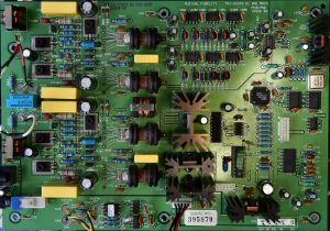
Now let’s turn our attention to the main PCB.
Figure 3: Main PCB (original)
Decoupling capacitors – stick with ceramics but use low-loss non-microphonic C0G types
If you are reading this you are no stranger to capacitors. I will leave you to decide whether you are going to increase capacitance or stick with original values. I would like to offer the following suggestions.
a. High frequency decoupling: There are about 50 low quality 0.1uF disc ceramic capacitors providing power supply decoupling onto the ground plane. Replace these with 0.1uF ceramic C0G. Remember this is a digital board with a 50MHz clock so you need caps that are good to at least 1GHz. Save your plastic films for analog stuff.
b. Low frequency decoupling: There are about 25 Jamicon brand electrolytics ranging from 10uF to 1000uF. I would go for 105C rating since you don’t want to do this again in the next 10 years. I stayed with Nichicon UKA because some 3 terminal regulators are said to be unstable with OSCON on the output. If you use OSCON, please let me know how it went. Some electrolytics provide critical voltage reference to the DAC chip and I will talk about these in the appropriate section.
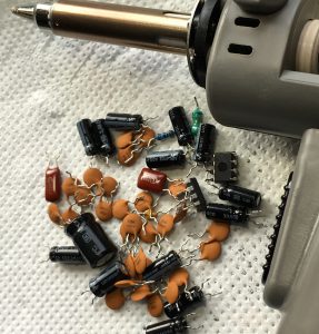
Figure 4: Removing the cheap original capacitors